7 Proven Steps to Use an OTDR to Test Fiber Optic Splices Like a Pro
If you work with fiber optic networks, knowing how to use an OTDR to test fiber optic splices is one of the most powerful skills you can have. Whether you’re commissioning a new installation or diagnosing mysterious signal loss, an Optical Time Domain Reflectometer (OTDR) gives you a precise, visual map of every splice, bend, and break across the entire fiber run.
Without proper OTDR testing, even a perfectly installed fiber network can hide failing splices that cause intermittent outages, degraded throughput, or complete link failure — often at the worst possible moment.
This guide walks you through 7 proven, step-by-step methods to confidently use an OTDR to test fiber optic splices, read and interpret results, and make smart decisions about when to re-splice and when to sign off.
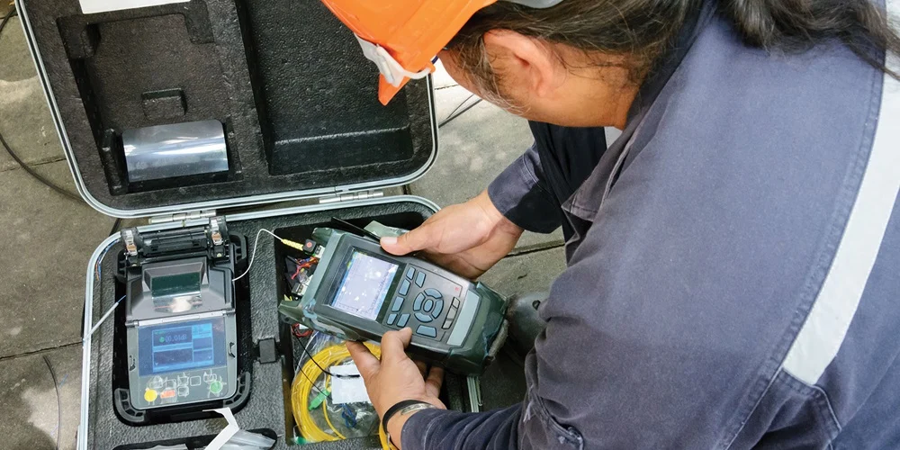
Show Image Alt text: technician using OTDR to test fiber optic splices
Table of Contents
- What Is an OTDR and Why Does It Matter?
- Why You Must Use an OTDR to Test Fiber Optic Splices
- Equipment You Need Before Testing
- 7 Proven Steps to Use an OTDR to Test Fiber Optic Splices
- How to Read an OTDR Trace
- Acceptable Splice Loss Values
- Critical Mistakes to Avoid
- OTDR Testing Standards
- When to Re-Splice vs. Accept the Result
- Conclusion
What Is an OTDR and Why Does It Matter? {#what-is-an-otdr}
An OTDR (Optical Time Domain Reflectometer) is a specialized test instrument that sends short laser light pulses into a fiber optic cable and measures the light reflected back. It uses the time delay and intensity of those reflections to calculate:
- The precise distance to every splice, connector, or fault along the cable
- The amount of optical loss at each event
- The overall attenuation (signal loss per kilometer) of the fiber
The result is a visual trace — a graph showing the entire fiber run from one end to the other. Every splice appears as a recognizable feature on that trace, giving you undeniable proof of splice quality.
Think of it like an ultrasound for your fiber — a non-destructive way to see inside the cable without disturbing the installation.
Why You Must Use an OTDR to Test Fiber Optic Splices
Many technicians rely solely on the estimated loss reading shown on the fusion splicer screen after completing a splice. This is a dangerous shortcut. Here’s why you always need to use an OTDR to test fiber optic splices:
The splicer estimate can be wrong. Fusion splicers estimate loss based on fiber core alignment images — they do not measure actual optical performance. A splice that looks perfect on the splicer screen can still have elevated loss due to contamination, cleave angle issues, or fiber geometry mismatches.
The OTDR finds hidden problems. Mechanical damage, tight bends, and poor splice protector installation that occur after splicing won’t show up on the splicer — but they will appear clearly on an OTDR trace.
Documentation is non-negotiable. OTDR test records are required for most professional installations. They serve as legal proof that the network was delivered within specification, and as a baseline for all future troubleshooting.
Standards require it. TIA-568, IEC 61280-4-1, and other major fiber standards specify OTDR testing as a mandatory part of the acceptance testing process. Learn more about testing requirements at the Fiber Optic Association (FOA).
Equipment You Need Before Testing
Before you use an OTDR to test fiber optic splices, confirm you have the following:
- OTDR unit — matched to the fiber type (single-mode or multimode) and the correct wavelength (1310/1550 nm for single-mode; 850/1300 nm for multimode)
- Launch cable / launch reel — at least 100–500 m of fiber to push the first splice past the OTDR’s dead zone
- Receive cable / tail reel — fiber at the far end to make the last splice fully measurable
- Fiber optic cleaning kit — lint-free wipes and 99% isopropyl alcohol (IPA)
- Fiber inspection scope — to visually confirm connector cleanliness before connecting
- Optical power meter — for supplemental end-to-end loss verification
⚠️ Critical: Never connect an OTDR to a live fiber carrying optical signals. Always confirm the fiber is dark before testing.
7 Proven Steps to Use an OTDR to Test Fiber Optic Splices
Step 1: Clean Every Connector Thoroughly
Contamination is the single biggest cause of inaccurate OTDR readings — and the most preventable. Before connecting anything, clean all connectors and the OTDR port with lint-free wipes and IPA. Inspect every end face under a fiber scope. A contaminated connector can also physically damage the OTDR’s internal optics, leading to costly repairs.
Clean. Inspect. Connect. In that order, every time.
Step 2: Connect the Launch Cable
Connect your launch cable between the OTDR output port and the start of the fiber run under test. The launch cable is essential because every OTDR has a dead zone — a short distance near the instrument port where the detector is overwhelmed by the initial pulse reflection and cannot accurately measure events.
Without a launch cable, your very first splice will fall inside this dead zone and be invisible or misread. The launch cable shifts that dead zone onto the reel, safely out of the way.
- Single-mode fiber: use at least 100–200 m
- Multimode fiber: 50–100 m is typically adequate
Show Image Alt text: fiber optic OTDR launch cable reel used to test fiber optic splices
Step 3: Connect the Receive (Tail) Cable at the Far End
At the opposite end of the cable run, connect your receive cable before the fiber terminates. This serves the same purpose as the launch cable — it moves the far-end dead zone onto the tail reel, ensuring the final splice on your actual cable is fully visible and measurable.
Skipping the tail cable is one of the most common field mistakes. It leaves the last splice partially hidden and prevents accurate loss measurement.
Step 4: Configure the OTDR Settings Correctly
Correct OTDR configuration directly determines the accuracy of your splice loss readings. Set these parameters carefully:
- Wavelength: Match to the operational wavelength of the fiber (1310 nm or 1550 nm for single-mode; 850 nm or 1300 nm for multimode)
- Distance range: Set at least 20% beyond the actual cable length. For a 5 km run, set 6 km or more.
- Pulse width: Shorter for better resolution on short cables; longer for extended range on long runs. Use auto-mode if available.
- Index of Refraction (IOR): Must match the fiber manufacturer’s datasheet exactly. An incorrect IOR causes every distance measurement to be wrong.
- Averaging time: Use a minimum of 60 seconds. For long runs or noisy environments, 120–180 seconds gives a cleaner, more accurate trace.
Step 5: Run the OTDR Scan
With everything connected and configured, initiate the OTDR scan. The instrument fires multiple laser pulses, collects the return data, and averages the results to reduce noise. Once complete, the OTDR generates and displays the full trace on screen.
Do not disconnect anything until you have reviewed the trace and confirmed all splice events are visible and within specification.
Step 6: Save the Trace Immediately
Save the OTDR trace as soon as the scan completes — before moving any cables or making any changes. Use the standard Bellcore SR-4731 (.sor) format for maximum compatibility with OTDR analysis software.
Label every saved trace with:
- Cable ID and route name
- Fiber number and color code
- Wavelength used
- Test direction (A-to-B or B-to-A)
- Date, location, and technician name
These saved traces become your permanent installation record. They are essential for warranty claims, future troubleshooting, and network maintenance planning.
Step 7: Test from Both Ends and Average the Results
This is the step most technicians skip — and it leads to incorrect splice loss values. Always use an OTDR to test fiber optic splices from both ends of every fiber.
Why? Because an OTDR measures backscatter, and if two fibers being spliced have different backscatter coefficients (which is common), the splice will appear to have higher loss in one direction and lower (or even “negative”) loss in the other. Neither reading alone is accurate.
True splice loss = (Reading A-to-B + Reading B-to-A) ÷ 2
Bi-directional averaging is required by TIA-568 and IEC 61280-4-1 for accurate, standards-compliant splice loss reporting.
How to Read an OTDR Trace
The OTDR trace is a graph with distance on the X-axis and signal level (dB) on the Y-axis. Understanding what you see is critical when you use an OTDR to test fiber optic splices:
- Downward slope — Normal fiber attenuation. A steeper slope means higher loss per kilometer.
- Step down (no spike) — A fusion splice or bend. The height of the step = splice loss in dB.
- Spike then step down — A mechanical connector, broken fiber end, or contamination point. The spike is a Fresnel reflection.
- Noise floor — The end of the fiber. The trace drops into random noise once the signal is gone.
- Ghost events — False reflections appearing at exact multiples of a real event’s distance. These are caused by strong reflections bouncing back and forth; they are not real faults.
Show Image Alt text: annotated OTDR trace showing how to read fiber optic splice loss events
Acceptable Splice Loss Values {#splice-loss-values}
When you use an OTDR to test fiber optic splices, these are the loss thresholds to work to:
| Splice Type | Typical Loss | Maximum Acceptable Loss |
|---|---|---|
| Fusion splice — single-mode | ≤ 0.05 dB | ≤ 0.10 dB |
| Fusion splice — multimode | ≤ 0.10 dB | ≤ 0.20 dB |
| Mechanical splice | ≤ 0.20 dB | ≤ 0.30 dB |
Always verify against your specific project specification, as some high-performance or long-haul networks require tighter limits than these general guidelines.
Critical Mistakes to Avoid {#mistakes}
Even experienced technicians make these errors when using an OTDR to test fiber optic splices:
- Skipping the launch cable — The first splice is hidden in the dead zone and cannot be accurately measured.
- Skipping the tail cable — The last splice is hidden or misread.
- Testing only one direction — Without bi-directional averaging, splice loss values are unreliable.
- Not cleaning connectors — Dirty connectors produce false events, inaccurate loss readings, and can damage the OTDR.
- Wrong IOR setting — Every distance measurement will be offset. Always confirm IOR from the fiber datasheet.
- Short averaging time — A noisy trace buries small splice events in the noise floor.
- Not saving traces — Without records, you have no baseline for future troubleshooting or warranty claims.
OTDR Testing Standards
Always perform and document OTDR splice testing in compliance with a recognized industry standard:
- TIA-568.3-D — North American standard for optical fiber cabling and testing
- IEC 61280-4-1 — International standard for field testing of installed single-mode fiber links
- IEEE 802.3 — Relevant for fiber used in Ethernet network infrastructure
Confirm which standard applies to your project before testing begins, and document compliance in your test reports.
When to Re-Splice vs. Accept the Result
Not every high reading means you need to re-splice. Use this decision framework:
Re-splice when:
- Bi-directional averaged loss exceeds the project specification
- A reflective spike is present at the splice point (indicates a gap or contamination)
- Loss is significantly higher than other splices on the same cable drum (suggests a technique or equipment issue)
Accept when:
- Bi-directional averaged loss is within specification
- The overall link loss budget is satisfied even with a slightly elevated splice
- Re-splicing at that location poses more risk than the marginal excess loss
When in doubt, re-splice. The materials and labor for a re-splice cost far less than an emergency site visit to fix a splice that fails in service.
Conclusion
Knowing how to correctly use an OTDR to test fiber optic splices is not just a technical skill — it is the foundation of professional fiber installation. By following these 7 proven steps, reading traces accurately, averaging bi-directional results, and documenting your work to industry standards, you can deliver fiber optic networks that perform reliably for decades.
An OTDR doesn’t just find problems after they happen. Used systematically, it prevents them from ever reaching your customers.
Need expert fiber optic testing, splice verification, or network commissioning support? Contact our certified fiber specialists today.
Related posts:
- 10 Critical Reasons Fiber Splices Fail After Installation
- Fusion Splicing vs. Mechanical Splicing: Which Is Right for Your Project?
- Top 10 Fiber Optic Installation Mistakes and How to Avoid Them
Leave a Reply